4. Multiple Winding Transformers
4. Multiple Winding Transformers
But the beauty of transformers is that they allow us to have more than just one winding in either the primary or secondary side. Transformers which have more than one winding are known commonly as Multiple Winding Transformers.
The principal of operation of a multiple winding transformer is no different from that of an ordinary transformer. Primary and secondary voltages, currents and turns ratios are all calculated the same, the difference this time is that we need to pay special attention to the voltage polarities of each coil winding, the dot convention marking the positive (or negative) polarity of the winding, when we connect them together.
Multiple winding transformers, also known as a multi-coil, or multi-winding transformer, contain more than one primary or more than one secondary coil, hence their name, on a common laminated core. They can be either a single-phase transformer or a three-phase transformer, (multi-winding, multi-phase transformer) the operation is the same.
Multiple Winding Transformers can also be used to provide either a step-up, a step-down, or a combination of both between the various windings. In fact a multiple winding transformers can have several secondary windings on the same core with each one providing a different voltage or current level output.
As transformers operate on the principal of mutual induction, each individual winding of a multiple winding transformer supports the same number of volts per turn, therefore the volt-ampere product in each winding is the same, that is NP/NS = VP/VS with any turns ratio between the individual coil windings being relative to the primary supply.
In electronic circuits, one transformer is often used to supply a variety of lower voltage levels for different components in the electronic circuitry. A typical application of multiple winding transformers is in power supplies and triac switching converters. So a transformer may have a number of different secondary windings, each of which is electrically isolated from the others, just as it is electrically isolated from the primary. Then each of the secondary coils will produce a voltage that is proportional to its number of coil turns for example.
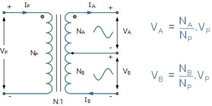
Multiple Winding Transformer
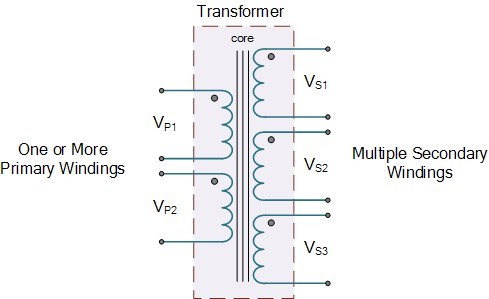
Above shows an example of a typical “multiple winding transformer” which has a number of different secondary windings supplying various voltage levels. The primary windings can be used individually or connected together to operate the transformer from a higher supply voltage.
The secondary windings can be connected together in various configurations producing a higher voltage or current supply. It must be noted that connecting together in parallel transformer windings is only possible if the two windings are electrically identical. That is their current and voltage ratings are the same.
Dual Voltage Transformers
There are a number or multiple winding transformers available which have two primary windings of identical voltage and current ratings and two secondary windings also with identical voltage and current ratings. These transformers are designed so that they can be used in a variety of applications with the windings connected together in either a series or parallel combinations for higher primary voltages or secondary currents. These types of multiple winding transformers are more commonly called Dual Voltage Transformers as shown.
Dual Primary & Dual Secondary Transformer.
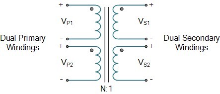
Here the transformer has two primary windings and two secondary windings, four in total. The connections to the primary or secondary windings must be made correctly with dual voltage transformers. If connected improperly, it is possible to create a dead short that will usually destroy the transformer when it is energized.
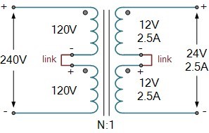
We said previously that dual voltage transformers can be connected to operate from power supplies of different voltage levels, hence their name “dual voltage transformers”. Then for example, let’s say that the primary winding could have a voltage rating of 240/120V on the primary and 12/24V on the secondary. To achieve this, each of the two primary windings is, therefore, rated at 120V, and each secondary winding is rated at 12V. The transformer must be connected so that each primary winding receives the proper voltage. Consider the circuit below.
Series Connected Secondary Transformer
Here in this example, the two 120V rated primary windings are connected together in series across a 240V supply as the two windings are identical, half the supply voltage, namely 120V, is dropped across each winding and the same primary current flows through both. The two secondary windings rated at 12V, 2.5A each are connected in series with the secondary terminal voltage being the sum of the two individual winding voltages giving 24 Volts.
As the two windings are connected in series, the same amount of current flows through each winding, then the secondary current is the same at 2.5 Amps. So for a series connected secondary, the output in our example above is rated at 24 Volts, 2.5 Amps. Consider the parallel connected transformer below.
Parallel Connected Secondary Transformer
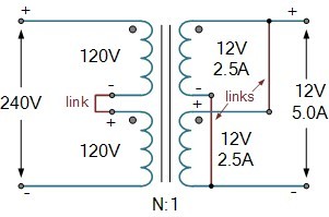
Here we have kept the two primary windings the same, but the two secondary windings are now connected in a parallel combination. As before, the two secondary windings are rated at 12V, 2.5A each, therefore the secondary terminal voltage will be the same at 12 Volts, but the current adds. Then for a parallel connected secondary, the output in our example above is rated at 12 Volts, 5.0 Amps.
Of course, different dual voltage transformers will produce different amounts of secondary voltage and current, but the principal is the same. Secondary windings must be correctly connected together to produce the required voltage or current output.
Dot orientation is used on the windings to indicate the terminals that have the same phase relationship. For example, connecting two secondary windings together in opposite dot-orientation will cause the two magnetic fluxes to cancel each other out resulting in zero output.
Another type of dual voltage transformer which has only one secondary winding that is “tapped” at its electrical center point is called the Center-tap Transformer.
Center Tapped Transformers
A center-tap transformer is designed to provide two separate secondary voltages, VA and VB with a common connection. This type of transformer configuration produces a two-phase, 3-wire supply.
The secondary voltages are the same and proportional to the supply voltage, VP, therefore power in each winding is the same. The voltages produced across each of the secondary winding is determined by the turns ratio as shown.
The Center-tap Transformer
Above shows a typical center-tap transformer. The tapping point is in the exact center of the secondary winding providing a common connection for two equals but opposite secondary voltages. With the center-tap grounded, the output VA will be positive in nature with respect to the ground, while the voltage at the other secondary, VB will be negative and opposite in nature, that is they are 180o electrical degrees out-of-phase with each other.
However, there is one disadvantage of using an ungrounded center tapped transformer and that is it can produce unbalanced voltages in the two secondary windings due to unsymmetrical currents flowing in the common third connection because of unbalanced loads.
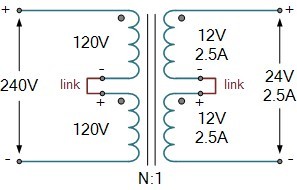
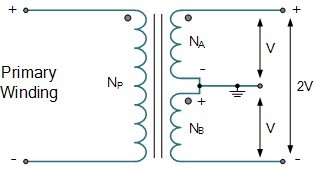
We can also produce a center-tap transformer using the dual voltage transformer from above. By connecting the secondary windings in series, we can use the center link as the tap as shown. If the output from each secondary is V, the total output voltage for the secondary winding will be equal to 2V as shown.
Center-tap Transformer using a Dual Voltage Transformer
Multiple Winding Transformers have many uses in electrical and electronic circuits. They can be used to supply different secondary voltages to different loads. Have their windings connected together in series or parallel combinations to provide higher voltages or currents, or have their secondary windings connected together in series to produce a center tapped transformer.
In the next tutorial about Transformers we will look at how Autotransformers work and see that they have only one main primary winding and no separate secondary winding.
References
This article is reprinted from Electronics Tutorials - Multiple Winding Transformers.